


Empresa
18 November 2026
Temporary Power Distribution Boxes: Uses and Sourcing Guide
A temporary power distribution box is a portable enclosure that takes one incoming supply …
 16:41
Poorly planned cable routes can create overloaded brackets, damaged wiring, and difficult maintenance. These problems grow as buildings add more equipment. A properly designed cable tray system, with suitable supports and accessories, helps protect cables, simplify installation, and keep industrial electrical infrastructure organized.
Um sistema de bandejas de cabos is a structural pathway that holds and organizes electrical wiring. It normally includes straight sections, brackets, hangers, connectors, bends, and covers. The correct design depends on cable weight, support spacing, environmental conditions, available space, installation method, and applicable electrical standards.
A cable tray system provides a fixed pathway for power, control, communication, and data wiring. It keeps each cable supported along a planned route instead of leaving long runs loose above equipment or inside service spaces.
The system consists of straight sections and compatible fittings. Brackets and hangers transfer the load to a building structure, while bends and connectors allow the pathway to change direction.
Compared with installing separate conduits for every circuit, a suitable open pathway can make cable management easier, particularly in facilities that frequently add or move equipment.
As aplicações comuns incluem:
In each application, the goal is to create an accessible and organized pathway that can carry the expected wiring load.
For example, a manufacturing facility may need separate routes for motor power, control signals, and network connections. The designer must consider physical separation, electromagnetic interference, cable ratings, and future expansion.
A well-planned pathway improves access and organization. However, it does not replace correct electrical protection, conductor sizing, bonding, or compliance with local codes.
Different cable tray types provide different levels of ventilation, cable support, protection, and installation flexibility.
The most common configurations include ladder, perforated, solid-bottom, channel, and wire-mesh systems.
| Type | Main structure | Common application | Main advantage |
|---|---|---|---|
| Ladder | Two side rails connected by rungs | Large power and control cables | Ventilation and accessible cable runs |
| Perforated | Formed bottom with regular openings | Mixed industrial wiring | Continuous support with airflow |
| Solid-bottom | Unperforated base | Smaller or sensitive wiring | Full bottom support |
| Channel | Narrow formed section | Small wiring groups | Compact installation |
| Wire mesh | Welded basket structure | Data and communications | Flexible routing and visibility |
A ladder structure often suits larger power cables because the open bottom allows airflow and easy inspection. Its load rating depends on the rail shape, rung spacing, steel thickness, and support span.
A wire mesh cable tray uses a basket structure. The term wire mesh cable support is also common in data cabling projects. Some installers call this a wire tray, especially when discussing lightweight network pathways.
Wire-mesh products can be convenient where the route needs frequent changes. However, field modifications must follow the manufacturer’s approved cutting, connection, finishing, and bonding methods.
Solid-bottom designs offer a continuous base but require attention to heat buildup, dust, moisture, and drainage.
The most suitable design is the one that meets the wiring requirements, building conditions, and approved load calculations—not simply the lightest or cheapest option.
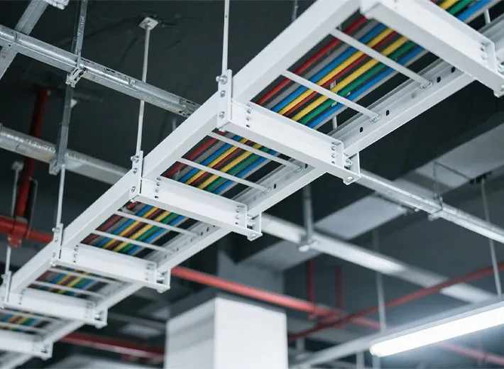
The support arrangement is one of the most important elements of a reliable overhead pathway. Even a strong metal section may bend or fail if its brackets, anchors, or spacing are unsuitable.
A correct design considers the total cable weight, tray self-weight, span, concentrated loads, and expected future additions.
Common mounting options include:
The correct spacing depends on the manufacturer’s structural ratings, product type, load, and project conditions. It should never be selected from appearance alone.
For a ceiling route, installers commonly use threaded rods and trapeze supports. These transfer the load to approved structural attachment points.
A hanging arrangement requires suitable rods, anchors, washers, nuts, channels, and restraints.
The designer must verify that both the support assembly and the building attachment can carry the specified loads.
A wall bracket is useful for horizontal routes along service corridors, production areas, and equipment rooms.
The bracket must resist vertical loading and bending forces. Its performance depends on arm length, profile geometry, anchoring, and the wall material.
A masonry wall, concrete wall, and lightweight partition do not provide the same attachment conditions.
For customized projects, accurately formed brackets and mounting channels are important because small dimensional errors can affect alignment across long runs.
Chenlong supplies cold-formed steel cable tray profiles and related metal components according to customer drawings, materials, and manufacturing requirements.
A complete pathway requires more than straight sections.
Cable tray accessories connect, redirect, reinforce, protect, and anchor the system so that it functions as one assembly.
Common components include:
| Accessory | Função | Key selection factor |
| Splice plate | Joins straight sections | Alignment and connection strength |
| Horizontal elbow | Changes direction | Bend radius |
| Vertical elbow | Changes elevation | Cable bending requirements |
| Tee fitting | Creates a branch route | Load and connection geometry |
| Cross fitting | Connects four directions | Structural coordination |
| Reducer | Connects different widths | Cable space and transition |
| Divider | Separates wiring groups | Required separation |
| Cover | Protects exposed wiring | Environment and fastening |
| End plate | Finishes an open end | Edge safety |
| Expansion connector | Accommodates movement | Temperature and length |
| Bracket | Supports the pathway | Load and attachment method |
Each component should match the straight section in geometry, material, finish, and approved connection method.
An elbow must also respect the minimum bend radius of the installed cable.
A sharp corner may be easy to fabricate but unsuitable for large power conductors or delicate communication wiring.
For industrial buyers, ordering a complete accessory kit can simplify procurement when it includes the correct splice plates, brackets, covers, bolts, washers, and other specified hardware.
It is also important to maintain electrical continuity across joints where required. A simple mechanical connection does not automatically prove that the necessary bonding path exists.
When manufacturers develop custom accessories, Chenlong can evaluate cold-formed connectors, reinforcing profiles, bracket channels, and other components based on technical drawings.
Good routing begins before the first bracket is installed.
The project team should study equipment locations, building columns, beams, doors, ventilation ducts, fire barriers, and future service access.
A practical design process includes:
Horizontal routes
Horizontal runs should remain properly aligned, with joints and fittings placed according to the selected product’s instructions.
Designers should avoid unnecessary direction changes. Every extra bend may increase pulling effort and add accessories.
Vertical routes
Vertical arrangements need appropriate restraints and cable fastening to prevent excessive strain.
The design should also account for gravity, cable weight, and entry points into electrical equipment.
Transitions to equipment
Where a pathway meets an enclosure, conduit, or machine, the transition should not leave wires unsupported or exposed to sharp edges.
Use suitable drop-out fittings, edge protection, and approved fixing methods.
According to the Cable Tray Institute’s codes and standards guidance, NEMA VE 2 provides guidance for handling, installing, maintaining, and modifying metal tray systems.
These guidelines should be used together with the applicable electrical code, project drawings, and manufacturer instructions.
Material selection has a direct effect on corrosion resistance, strength, weight, manufacturing methods, and long-term performance.
Common options include carbon steel, galvanized products, aluminum, and stainless steel.
| Material or finish | Typical environment | Main consideration |
| Aço pré-galvanizado | Dry indoor buildings | Economical zinc-coated material |
| Hot-dip galvanized steel | Outdoor and industrial locations | Protection after fabrication |
| Aço inoxidável | Coastal, chemical, or washdown environments | Corrosion resistance |
| Alumínio | Weight-sensitive applications | Low weight and corrosion behavior |
| Painted steel | Controlled indoor conditions | Coating quality and damage protection |
For many commercial projects, galvanized metal offers a practical balance of cost and corrosion resistance.
Manufacturers may form pre-coated material or galvanize certain components after fabrication, depending on the specification.
Post-fabrication treatment can cover cut edges and processed areas, but coating buildup must be considered where parts connect or fit together.
A stainless construction may be suitable where salt, moisture, chemicals, or cleaning procedures create demanding conditions.
For indoor and outdoor use, engineers should also review:
A heavy duty system may need stronger formed sections and closer structural review, not merely a thicker coating.
For long-lasting performance, the selected material and protective treatment must match the real operating environment.
Correct installation is essential for safety and service life.
Workers should follow the approved drawings and instructions rather than modifying sections or changing bracket locations without review.
Before energizing the electrical system, check:
A pathway should not be used as a walkway, platform, or working surface unless it has been specifically designed and approved for that purpose.
The Cable Tray Institute’s technical questions explain that personnel should not walk on installed cable trays.
Maintenance teams should look for corrosion, damaged hardware, unsupported additions, loose connectors, and changes to the operating environment.
Manufacturing quality affects how easily parts connect, align, and carry their intended loads.
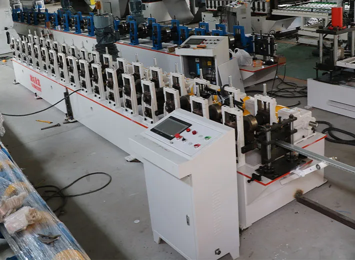
The main production stages may include cutting, punching, roll forming, bending, joining, finishing, and inspection.
For repeated metal profiles, cold roll forming is a practical manufacturing method.
A typical process may follow:
A production line may perforate the flat strip before bending it into a tray section.
The forming stations gradually shape the side walls, edges, and reinforcing features.
Accurate hole placement helps splice plates, brackets, and covers fit correctly during assembly.
For manufacturers that need to reinforce a profile, the design may include additional folds, ribs, or suitable strengthening features.
These details can improve stiffness, but the final load performance still requires engineering verification.
uld also check that later modifications have not reduced structural performance or created unsafe wiring conditions.
Consider a factory that produces straight sections and connector profiles using separate punching, cutting, and bending equipment.
Workers move material from one station to another. Repeated handling adds labor, creates queues, and makes it harder to keep hole positions consistent.
A customized forming line can connect feeding, punching, forming, and cutting operations.
Potential benefits include:
The exact gains depend on material thickness, product geometry, output requirements, and process configuration.
Na Weifang Chenlong Intelligent Technology Co., Ltd., our engineers review product drawings and samples before developing a forming solution.
The goal is not only to manufacture a profile faster. It is to produce components that fit together correctly and meet the customer’s technical requirements.
Chenlong is a high-tech manufacturer based in Shandong, China, specializing in precision cold bending equipment, customized automated production lines, and formed metal profiles.
Our work supports manufacturers, OEM partners, and distributors serving the electrical, construction, new-energy, and industrial equipment markets.
For companies that need formed components, Chenlong provides custom cold-formed cable tray profiles based on customer drawings and requirements.
For customers planning factory expansion, our cable tray cold-forming equipment production line integrates customized feeding, punching, forming, and cutting operations.
Our electrical cabinet and cable tray manufacturing solutions also connect profile development with automated metal processing.
To develop a practical proposal, provide:
| Information | What Chenlong needs |
| Product drawing | Cross-section and assembly details |
| Material | Grade, coating, and mechanical properties |
| Thickness | Required production range |
| Dimensions | Width, height, and cut length |
| Hole pattern | Shape, spacing, and position |
| Accessories | Brackets, connectors, covers, and rails |
| Production target | Expected output |
| Product range | Number of specifications |
| Automation | Manual receiving or automatic handling |
| Factory conditions | Voltage and available floor area |
| Quality requirements | Critical tolerances and inspection needs |
Our team reviews the profile geometry, forming sequence, tooling requirements, and production workflow before recommending equipment.
That approach helps buyers compare realistic manufacturing options rather than selecting a machine based only on headline speed or initial price.
For an OEM project, the cost also depends on tooling, material range, changeover requirements, labor, maintenance, and future expansion.
A supplier should explain these factors clearly before the buyer commits to a customized line.
What is the difference between a wire mesh tray and a ladder system?
A wire-mesh design uses welded metal wires to create an open basket, often suitable for network and data wiring. A ladder design uses two side rails and spaced rungs and is commonly selected for larger power and control circuits. Each has different load, span, and installation requirements.
Can a cable tray be mounted directly on a wall?
Yes, when suitable brackets and anchors are selected for the load and the supporting structure. Wall construction, bracket projection, attachment capacity, and installation conditions must be checked.
What accessories are needed for a ceiling-mounted installation?
Typical items include threaded rods, trapeze channels, brackets, anchors, nuts, washers, splice plates, and the required bonding components. The final list depends on the approved support design.
Can fiber optic and power cables share one pathway?
It may be possible under the applicable rules and cable specifications, but separation, interference, mechanical protection, and accessibility must be evaluated. Fiber optic connections and sensitive network wiring should not be placed without reviewing these requirements.
Does the tray itself insulate electrical wiring?
No. A metal pathway provides mechanical support and does not insulate conductors. The installed wiring must have the appropriate insulation and ratings, while bonding and grounding must meet the applicable requirements.
Can Chenlong produce custom brackets and tray profiles?
Yes. Chenlong develops cold-formed components and processing equipment from customer drawings or samples. The feasible product range depends on profile geometry, steel grade, thickness, punching details, tolerance, and production volume.
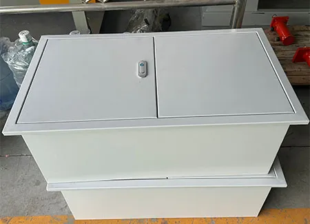
A temporary power distribution box is a portable enclosure that takes one incoming supply …
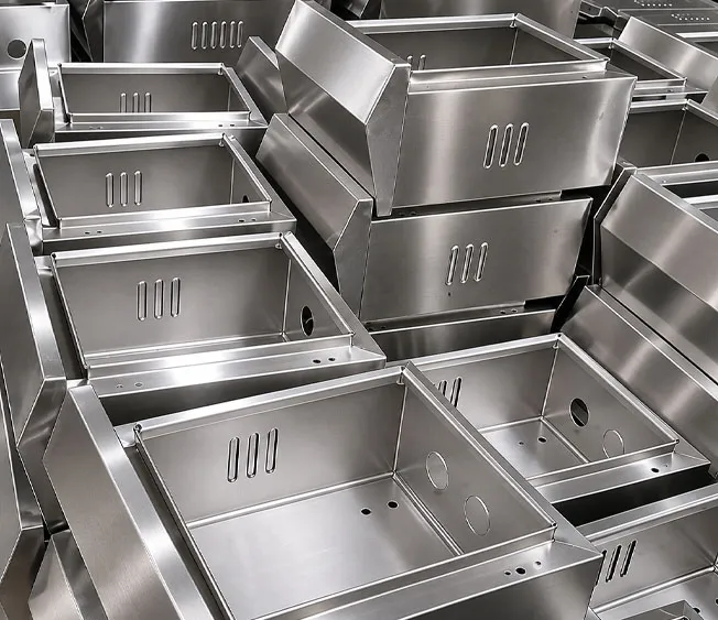
Seven electrical panel board types explained for cabinet and switchgear manufacturers, plu…
Responderemos dentro de 24 horas. Para casos urgentes, adicione WhatsApp/WeChat: +8613863639320. Ou ligue diretamente para +8613863639320.
*Respeitamos sua confidencialidade e todas as informações estão protegidas.
Usaremos suas informações apenas para responder à sua consulta e nunca enviaremos e-mails não solicitados ou mensagens promocionais.