











Компания
02 September 2026
Warehouse Racking Systems and Warehouse Shelving: How to Choose the Right Storage Solution
Poor storage planning wastes floor space, slows picking, and increases product damage. The…
 16:25
16:25 Loose electrical lines create blocked access, poor airflow, slow maintenance, and higher damage risk. In a large factory, these problems grow with every new circuit. A properly selected cable tray system keeps each cable organized, supported, visible, and easier to maintain.
A cable tray is a rigid support structure for electrical, control, and communication lines. The right system depends on cable load, span, environment, airflow, corrosion risk, available space, and local code. Common choices include ladder, perforated, solid-bottom, channel, and wire-mesh designs.
A кабельный канал is a mechanical structure that supports insulated electrical cables, communication lines, and other wiring. It creates a planned route through a building, plant, or infrastructure project. The National Electrical Manufacturers Association describes trays as rigid structural systems that support electrical cables, raceways, and insulated conductors.
Unlike a closed pipe, a tray normally leaves much of the wiring accessible. Workers can inspect, add, remove, or reroute lines without opening long sections of conduit. That makes this approach useful in commercial and industrial projects where systems change over time.
строительная промышленность: крыша, облицовка, стеновые панели, рамы, ограждения
A tray is not the same as a wireway or raceway. Each method has its own permitted uses, installation rules, fill limits, and protection requirements. The designer must select a method based on the real application—not simply on appearance or price.
A cable tray system creates a continuous, supported path between electrical equipment, control panels, machines, and service areas. It keeps long cable runs above floors and away from moving equipment when installed correctly.
Good cable management makes maintenance easier. Technicians can follow a circuit, identify a damaged section, and reach it without opening many closed covers. New lines can often be added with less disruption, provided the design still meets loading, separation, and code requirements.
A well-planned route can provide:
A tray also supports power distribution layouts in factories and large buildings. However, the cable tray provides mechanical support; it does not replace correct conductor selection, grounding, fire protection, circuit protection, or engineering review.
For industrial projects, cable routing should consider heat sources, sharp edges, moving machines, chemical exposure, vibration, moisture, fire barriers, and access paths. A neat route is useful. A safe route is essential.
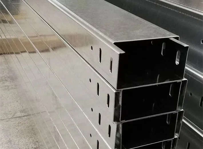
The right design depends on load, span, cable type, airflow needs, and the operating environment. The most common cable tray types include ladder, perforated, trough, channel, solid-bottom, and basket designs.
| Type | Structure | Typical Use | Main Advantage |
| Ladder | Two side rails with cross rungs | Large power and control cables | High strength and ventilation |
| Perforated | Bottom panel with punched openings | Mixed industrial wiring | Cable support with airflow |
| Solid Bottom | Fully enclosed base | Small or sensitive cables | Continuous cable support |
| Channel | Narrow U-shaped section | Small cable groups | Compact cable routing |
| Wire Mesh | Welded basket structure | Data and light communication cables | Flexible field modifications |
| Trough | Ventilated or partially enclosed base | Medium-sized cable groups | Balanced support and accessibility |
A ladder tray often suits long industrial routes and heavier loads. Its open structure helps ventilate the wiring and makes visual inspection simple. Rung spacing, side-rail height, width, and material thickness must match the project.
A perforated design gives more continuous support while allowing some ventilation. Manufacturers create the openings during punching or roll forming. Hole size and spacing affect weight, strength, airflow, and production requirements.
A channel кабельный канал is narrower. It often serves a small group of control, instrumentation, or branch lines where a wide structure is unnecessary. A cable channel can also help route wiring through compact machine areas.
A solid-bottom design offers continuous support but can hold heat, dust, or moisture if it is poorly specified. Engineers should assess whether the product needs drainage, covers, extra ventilation, or a different structure.
A ladder design uses two longitudinal side rails connected by rungs. It looks simple, but it can carry large bundles when properly designed. This structure is common in power plants, manufacturing sites, utility spaces, and other industrial environments.
It is often suitable when a project needs:
Open construction helps air move around the wiring. This can be valuable for a power cable or a group of conductors that generates heat. The designer must still calculate allowable fill, spacing, ampacity, and load rather than assuming that open construction removes every thermal limit.
Heavy power applications may require deeper side rails, closer supports, stronger rungs, or thicker material. The support structure beneath the tray also matters. A strong product can still fail if a hanger, bracket, or building connection is undersized.
A typical route may use horizontal sections, vertical sections, tees, crosses, reducers, and a 90 degree bend. Each fitting should preserve suitable bend radius and support. Poorly planned direction changes can place extra stress on the conductor or make pulling difficult.
A wire mesh design uses welded steel wires to create an open basket. It is light, visible, and often easy to modify in the field. Installers can form bends and changes with approved methods and connectors when the product instructions allow it.
A wire mesh cable support route is common in:
A wire mesh tray provides strong airflow and easy access. It can work well above server racks, below raised floors, or along walls. Because the system is open, dust, falling objects, electromagnetic concerns, and physical protection still need review.
Do not choose basket construction only because it is easy to install. Check load rating, support spacing, wire diameter, connector strength, grounding continuity, and cable type. Large power circuits may need a different design or careful engineering.
Where power, control, and communication wiring share a route, a divider may help maintain separation. A divider strip must match the tray and project requirements. Physical separation alone does not solve every interference or code issue.
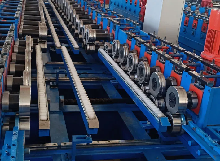
Material choice affects strength, service life, cost, weight, and corrosion resistance. Common options include carbon steel, galvanized steel, stainless steel, aluminum, and nonmetallic materials.
| Material or Finish | Suitable Conditions | Key Consideration |
| Pre-Galvanized Steel | Dry indoor and light-duty environments | Economical zinc-coated sheet |
| Hot-Dip Galvanized Steel | Industrial and outdoor environments | Stronger post-fabrication coating |
| Stainless Steel | Chemical, washdown, or coastal environments | Higher corrosion resistance |
| Алюминий | Projects requiring a lightweight solution | Electrical conductivity and mechanical design |
| Painted Steel | Controlled indoor environments | Coating damage and maintenance requirements |
Pre-galvanized steel receives its zinc coating before the tray is formed. It is also written as pre galvanized steel. Cutting, punching, and forming can expose small areas, so buyers should evaluate the environment before selecting it.
A product that is galvanized after fabrication receives its coating after cutting, punching, and joining. This process is commonly called hot dipped galvanized or hot-dip galvanized finishing. It can protect edges and fabricated areas more fully, although coating thickness and surface appearance differ from pre-coated sheet.
The phrase “hot dipped” describes the coating process, but a buyer still needs a clear specification. Ask about base metal, coating method, coating thickness, relevant standard, surface quality, and inspection.
For highly corrosive or hygiene-sensitive sites, 316 stainless steel may be more suitable. It often appears in coastal facilities, chemical processing, food plants, and washdown areas. Even stainless material requires a review of chemicals, temperature, cleaning method, and possible galvanic interaction with other metals.
The best materials and finishes depend on the full environment:
A manufacturer should not simply “galvanize more” without reviewing forming tolerances. Coating buildup can affect connection details, splice plates, holes, and fit between components.
Sizing begins with a full cable schedule. Record every line, outside diameter, weight, voltage class, function, bend radius, and future expansion need. Do not size the system from cable count alone.
The design should consider:
The structure must carry the installed wiring plus applicable construction, maintenance, wind, snow, seismic, or ice loads where relevant. A product rated for a certain uniform load may respond differently to a concentrated load from a worker, cable reel, or unsupported junction.
The designer should also consider thermal behavior. Tightly packed electrical cables can retain heat. An open design can improve ventilation, but correct spacing and ampacity calculations still matter. A tray cannot automatically ventilate every wiring arrangement well enough.
For mixed services, separate high-voltage, control, instrumentation, and telecommunications lines when required. A metallic cable structure may need bonding, grounding, and electrical continuity across each splice.
When planning future capacity, use a realistic growth allowance. Too little room makes expansion difficult. Too much empty width increases material, supports, and space requirements. The goal is a practical balance.
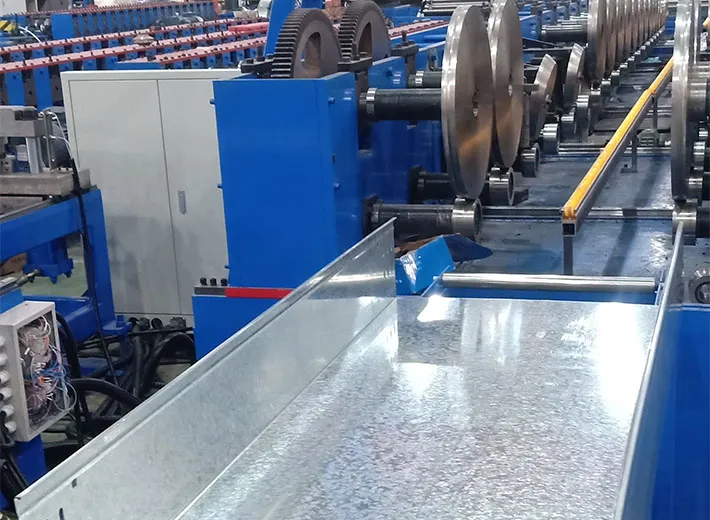
Good products can perform poorly if the installation is wrong. Supports must hold the route at proper intervals, joints must align, and accessories must preserve the intended loading capacity.
Common support methods include:
Supports should be placed according to the manufacturer’s instructions, engineering design, and applicable standard. Extra support may be needed near a fitting, vertical change, heavy connection, or concentrated load.
Cable tray fittings connect straight sections and change direction or width. Common parts include:
A splice joins adjacent sections. The connection must use the intended hardware and torque. Misaligned joints can damage wiring, weaken the route, and make later pulling difficult.
Plan the full route before work begins. Check equipment doors, fire barriers, pipework, HVAC ducts, walkways, and maintenance clearance. Good routing reduces field cutting and avoids sharp, crowded changes.
A standard cable tray should arrive with clear drawings and compatible accessories. If contractors must improvise every connection, the product may be harder to assemble consistently.
In the United States, the National Electrical Code, NFPA 70, is a central reference for electrical design and installation. Article 392 addresses cable trays. The applicable edition depends on the local authority, so always confirm which version the project has adopted. NFPA describes the NEC as a benchmark for safe electrical design, installation, and inspection.
NEMA also publishes standards for metal tray systems. NEMA VE 1 addresses requirements for metal systems, while NEMA VE 2 provides installation guidance. The NEMA Cable Tray section explains that these products mechanically support electrical wiring, raceways, and insulated conductors.
Standards may address:
The words cable tray systems for electrical projects do not define compliance by themselves. Engineers must check the exact product, cable type, location, fill, support arrangement, grounding method, and local rules.
The manufacturer should supply technical data for load ratings, spans, materials, finishes, and accessories. The installer should follow project drawings and product instructions. The authority having jurisdiction makes the final code decision.
A compliant product can still be installed incorrectly. A neat installation can still use the wrong product. Both selection and workmanship matter.
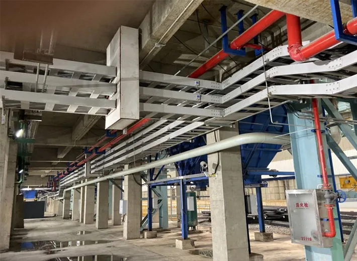
Manufacturers often struggle with slow punching, inconsistent holes, uneven side rails, repeated manual bending, and high handling costs. These issues grow when buyers request several widths, heights, lengths, and patterns.
At Weifang Chenlong Intelligent Technology Co., Ltd., we design high-precision cold bending forming equipment and customized automated lines for metal profile processing. Our cable tray cold-forming equipment production line can combine material feeding, leveling, punching, roll forming, cutting, and receiving in one production flow.
A typical automated line may include:
The machine can perforate the strip before forming. This helps keep repeated openings consistent across the finished part. Carefully designed rollers then shape the material step by step without using heat.
Consider a factory that makes perforated trays in several widths. Its workers first cut sheet, mark the holes, punch the pattern, move each blank, bend both sides, and measure the finished part. Every transfer adds time. Small position errors can also accumulate.
A customized line connects these steps. The control system feeds a set length, the press creates the pattern, and the forming stands shape the sides. The cut-off then produces the required length.
Potential gains include:
Results depend on material, thickness, product design, automation level, production speed, and changeover method. We do not treat every factory the same. We review drawings and real production goals first.
For buyers who need finished components instead of machinery, Chenlong also supplies cold-formed steel cable tray profiles. These can support ladder, perforated, channel, and customized designs based on the buyer’s drawings and application.
A capable cable tray manufacturer should understand more than sheet thickness and price. The supplier should ask how the product will be used, what it must carry, where it will operate, and how installers will connect each section.
Before requesting a quotation, prepare:
If you are purchasing manufacturing equipment, also explain the number of product sizes, changeover target, available factory space, electrical supply, labor plan, and downstream packaging process.
A good cable management solution must work from production through installation. Accurate profiles help parts align. Compatible fittings simplify assembly. Stable finishing supports service life. Clear labels and packaging help installers identify each component.
At Chenlong, we work with manufacturers, distributors, and OEM partners that need either custom profiles or an automated production line. Our electrical cabinet and cable tray solution connects equipment design, profile development, and industrial application support.
A cable tray used in an industrial building provides mechanical support and a planned route for power, control, instrumentation, or communication lines. It can make inspection, maintenance, and future expansion easier.
No. Conduit is a closed raceway, while trays generally provide an open or partly open support structure. Their permitted uses, fill rules, protection methods, and installation requirements differ.
Ladder construction is common for large conductors because it offers strength, open access, and airflow. However, the final choice must consider total load, span, bend radius, environment, and applicable rules.
A perforated product has punched openings that reduce weight and improve airflow. A solid-bottom product gives continuous support but may retain heat, dust, or moisture. Each is useful in different conditions.
A customized line may support several widths or heights through adjustable stands, tooling changes, or modular rollers. The actual range depends on the profile design, material, thickness, punching pattern, and machine configuration.
We need the cross-section drawing, material, thickness, width range, hole pattern, cut length, production target, required speed, and finished-product application. Samples and existing process information are also useful.
A reliable industrial route begins with a clear cable schedule, a suitable structure, the right material, and correct support spacing. It must also account for heat, corrosion, access, expansion, and code requirements.
For manufacturers, product quality begins even earlier. Accurate punching, stable forming, consistent length, and compatible accessories determine how efficiently each section can be assembled and installed.
Weifang Chenlong Intelligent Technology Co., Ltd. provides custom cold roll forming machinery and formed metal profiles for electrical equipment, new energy, structural systems, and industrial infrastructure. We help global manufacturers and OEM partners improve production through automation, customization, and integrated engineering support.
If you need a new production line or custom profiles, contact Chenlong with your drawings, material specifications, product range, and output target. We will review your project and propose a practical manufacturing approach built around your real needs.
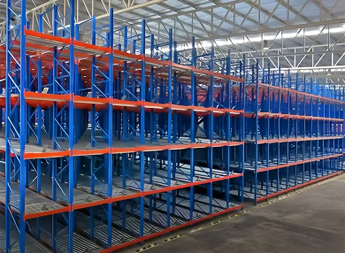
Poor storage planning wastes floor space, slows picking, and increases product damage. The…
Loose electrical lines create blocked access, poor airflow, slow maintenance, and higher d…
Мы ответим вам в течение 24 часов. Если для срочного случая, пожалуйста, добавьте WhatsApp/WeChat: +8613863639320,. Или позвоните по телефону +8613863639320.
*Мы уважаем вашу конфиденциальность и защищаем всю информацию.
Мы будем использовать вашу информацию только для ответа на ваш запрос и никогда не будем отправлять незапрашиваемые электронные письма или рекламные сообщения.